46 Results
View results:
Sort by:

RWIND 2 and RFEM 6 can now be used to calculate wind loads from experimentally measured wind pressures on surfaces. Basically, two interpolation methods are available to distribute pressures measured in isolated points across the surfaces. The desired pressure distribution can be achieved using the appropriate method and parameter settings.

Wind direction plays a crucial role in shaping the outcomes of Computational Fluid Dynamics (CFD) simulations and the structural design of buildings and infrastructures. It is a determining factor in assessing how wind forces interact with structures, influencing the distribution of wind pressures, and consequently, the structural responses. Understanding the impact of wind direction is essential for developing designs that can withstand varying wind forces, ensuring the safety and durability of structures. Simplified, the wind direction helps in fine-tuning CFD simulations and guiding structural design principles for optimal performance and resilience against wind-induced effects.
![Spans Based on Figure 5.2 from [1]](/en/webimage/039540/3493372/01_Abmessungen_EN.png?mw=640&hash=a3c436931baff3514db261b2d11bfa39abae9170)
In order to correctly design a downstand beam or a T-beam in RFEM 6 using the Concrete Design add-on, it is essential to determine the flange widths for the rib members. This article describes the input options for a two-span beam and the calculation of the flange dimensions according to EN 1992-1-1.

When a concrete slab is set upon the top flange, its effect is like a lateral support (composite construction), preventing problems of torsional buckling stability. If there is a negative distribution of the bending moment, the bottom flange is subjected to compression and the top flange is under tension. If the lateral support given by the stiffness of the web is insufficient, the angle between the bottom flange and the web intersection line is variable in this case so that there is a possibility of distortional buckling for the bottom flange.

In RFEM 6, the results for the FE mesh nodes are determined using the finite element method. For the distribution of internal forces, deformations, and stresses to be continuous, these nodal values are smoothed through an interpolation process. This article will introduce and compare the different types of smoothing that you can use for this purpose.
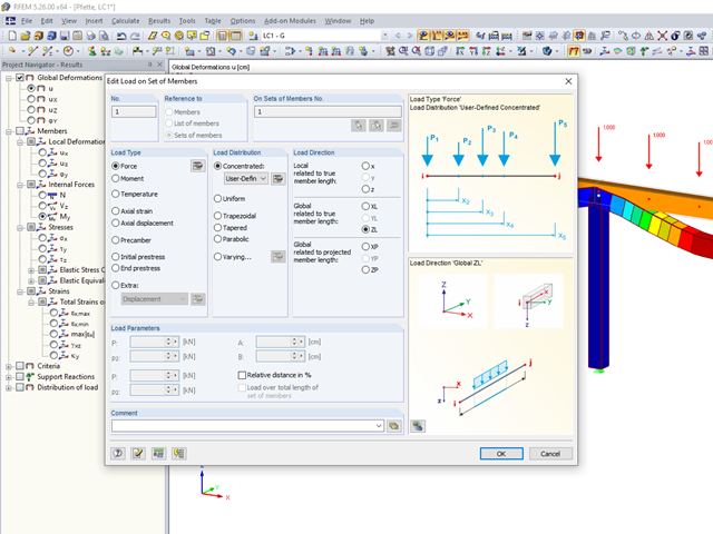
Arbitrary distributions of concentrated loads often occur in the load definition of beam structures.
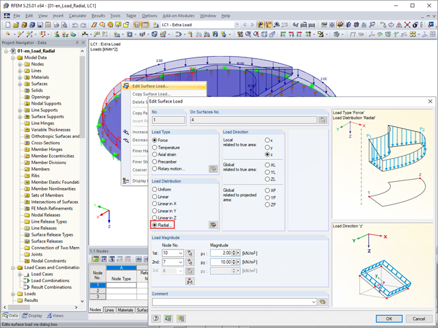
The "Radial" load distribution dialog box is available in RFEM for the quick generation of radial surface loads.

Designing vertical insulating glass requires assigning different loads on the individual layers of the entire glass unit. This occurs, for example, with simultaneous actions from wind loads and fall protection.

The German Annex to EN 1992‑1‑1, the National Addition NCI to Article 9.2.1.2 (2), recommends to dispose the tension reinforcement in the flange plate of T‑beam cross‑sections on a maximum of one width corresponding to the half of a computed effective flange width beff,i according to Expression (5,7a).

In order to detect the governing internal forces of a plate, a checkerboard loading is commonly used. Since it is not necessary to divide the surface into individual load segments, loading is usually carried out by means of free rectangular loads. In the case of many loads, the normal load display can become somewhat confusing.
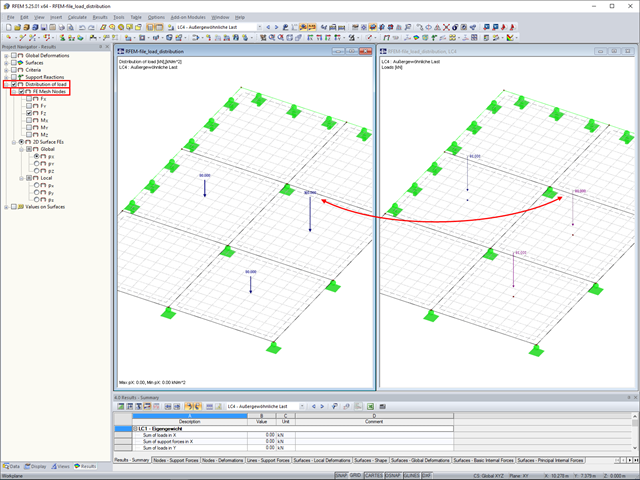
In RFEM, the load distribution is available for the result evaluation.
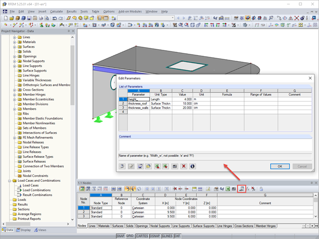
Parameterized entries provide the engineer with an efficiency-increasing tool. This allows entering structural and loading data so that they depend on certain variables. These variables (for example, length, width, live load, and so on) are called parameters.

The classification of cross-sections according to EN 1993-1-1 using Table 5.2 is a simple method for designing the local buckling of cross-section parts. For cross-sections of cross-section class 4, it is then necessary to determine the effective cross-section properties according to EN 1993-1-5 in order to consider the influence of local buckling in the ultimate limit state designs.
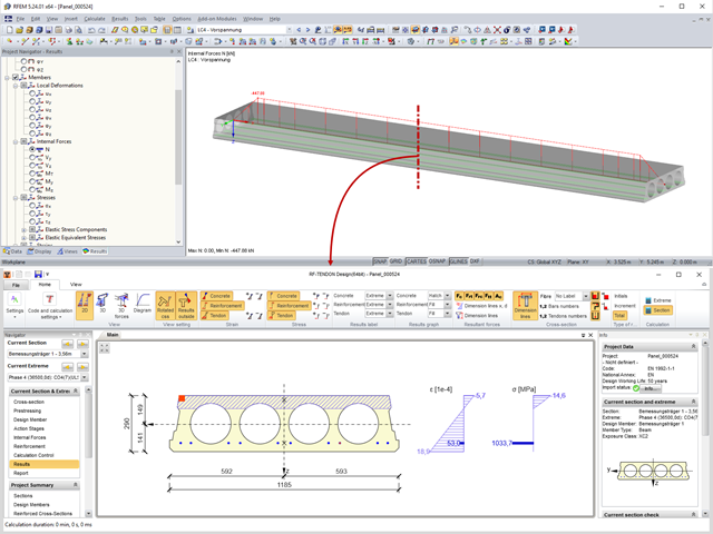
Prestressed concrete slabs consist of composite, uniaxially stressed hollow plates with a width of about 1.20 m. These elements are prestressed with pre-tension in a precast concrete plant. The precasting is usually done with slipformers. Due to the lesser self‑weight of the non‑solid slab and the existing prestress, these precast prestressed hollow core slabs show a lower deflection than loosely reinforced slabs made of solid concrete.
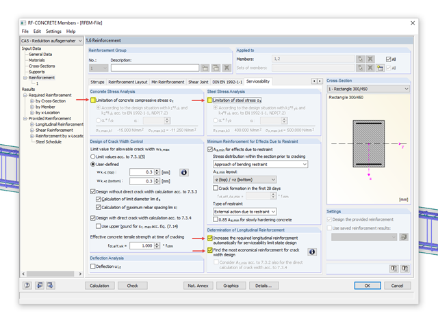
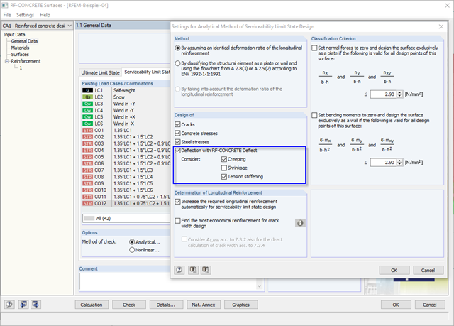
In Part 1, the selection of the design criteria for dimensioning the reinforcement for the serviceability limit state design in RF‑CONCRETE Members and CONCRETE was explained. Now, we go into detail for the function "Find economical reinforcement for crack width design".

When defining the effective slab width of T-beams, RFEM provides the predefined widths that are determined as 1/6 and 1/8 of the member length. A more detailed explanation on these two factors is given below.
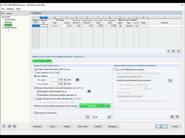
Eurocode 2 provides two ways to perform a crack width design. On one hand, the crack width design according to 7.3.3 can be performed without direct calculation by means of tables for the limitation of the member spacing and diameter. On the other hand, the crack width wk can be determined directly according to 7.3.4 and compared to a limit value.

Reinforced concrete surface design for slabs, plates, and walls is possible in the RF-CONCRETE Surfaces module according to the ACI 318-19 or the CSA A23.3-19 standard. A common approach for slab design is the use of design strips for determining the average one-way internal forces over the width of the strip. This design strip method essentially takes a two-way slab element and applies a simpler one-way approach to determine the required reinforcement needed along the strip length.

In the existing standard, there were no regulations for the distribution of snow loads for elevated solar thermal and photovoltaic systems on roofs. Only distribution of the loads was advised. It was only with the National Annex DIN EN 1991-1-3/NA: 2019-04 that specific regulations were made for this.

When evaluating line support forces, implausible diagrams sometimes arise at first glance. In particular, for variable loads at locations that also have a nodal support, at division points and edge locations of supported lines, the results sometimes show unexpected support reactions. Using the function of the linear smooth distribution in Project Navigator – Display does not always lead to the expected result diagram.
When calculating a surface model, the internal forces are determined separately for each finite element. Since the element-by-element results usually represent a discontinuous distribution, RFEM performs smoothing of the internal forces that takes into account the influence of adjacent elements. The discontinuous distribution of internal forces is adjusted with this method. The result evaluation is thus clearer and easier.
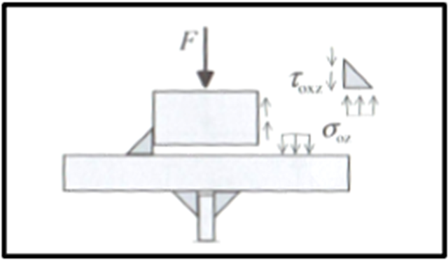
When performing control calculations and comparing the internal forces and the resulting required reinforcement of downstand beams, large differences can occur. Although the same load assumptions and spans are applied, some programs or the manual calculation display very different internal forces compared to the FEA model. The differences already occur in the case of the centric member and without considering the internal forces' components from the possible effective slab widths.
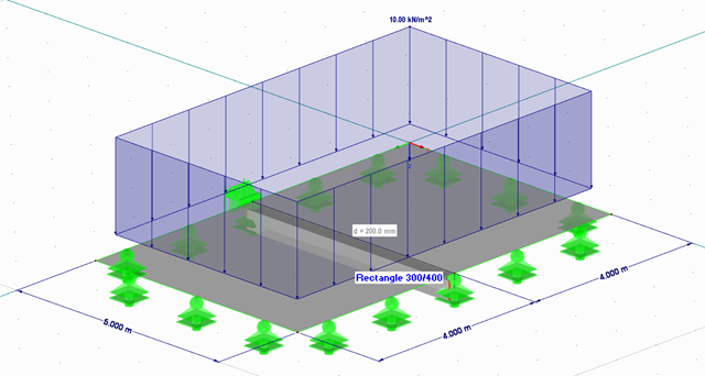
Performing serviceability limit state design also includes taking into account the allowable deformation. Calculating the deformation of reinforced concrete components depends on whether or not the observed cross-section cracks under the applied loading. The governing control parameter in RF-CONCRETE Deflect is the distribution coefficient ζ.
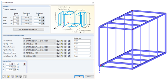
With the "Generate Model - Members" → "3D Cell" function, it is very easy to generate containers (shipping containers, office containers, mobile homes, and so on) with regular and irregular distribution of the cells.
![Tension Cover Line from [1]](/en/webimage/009390/2418541/01-en-png.png?mw=640&hash=c76563b459152b19c98197ea6ba342be89d9a5bc)
In the case of a large amount of reinforcement, it might be useful to grade the longitudinal reinforcement of a beam, which means: curtailment. The grading corresponds to the tensile force distribution. Using RF-CONCRETE Members and CONCRETE, you can specify the curtailment of the reinforcement, which is considered in the automatically proposed reinforcement for the longitudinal reinforcement. When determining this reinforcement proposal, it is necessary to ensure that the envelope of the acting tensile force can be absorbed.

Buckling analysis according to the effective width method or the reduced stress method is based on the determination of the system critical load, hereinafter called LBA (linear buckling analysis). This article explains the analytical calculation of the critical load factor as well as utilization of the finite element method (FEM).
![Parameters of Effective Slab Width (Figure 5.3 [1])](/en/webimage/009561/2419376/01-en-png.png?mw=640&hash=c76563b459152b19c98197ea6ba342be89d9a5bc)
In the case of combined FEM structures (surface and member elements) as well as folded plate structures, it is possible to attribute a beam structure for the design on a member to a fictitious T-beam cross-section, whose geometry depends on the effective width. When using the "Rib" member type in RFEM, the stiffness is represented by a slab component (surface element) and a web component (member element). This approach has some design specifics that are explained in this article.
Based on the technical article about the ultimate limit state design of rail welds, the following explanation refers to the process of fatigue design of rail welds. In particular, this article explains in detail the effects of considering an eccentric wheel load of 1/4 of the rail head width.
![Residual Stresses, Zero Line Position, and Tearing Depth when Cooling Pane on both Sides [2]](/en/webimage/009621/2419687/01-en-png-png.png?mw=640&hash=5e657e3feb5c1bb6d21727468dd85d91e1c9f29f)
Generally, avoiding cracking in concrete structures is neither possible nor necessary. However, cracking must be limited in a way so that the proper use, appearance, and durability of the structure are not affected. Therefore, limiting the crack width does not mean preventing from the crack formation, but restricting the crack width to harmless values.
![Time-Dependent Settlement Components [2]](/en/webimage/009673/2419908/01-en-png-png.png?mw=640&hash=5e657e3feb5c1bb6d21727468dd85d91e1c9f29f)
For the serviceability limit state design according to Section 6.6 of Eurocode EN 1997‑1, settlement has to be calculated for spread foundations. RF-/FOUNDATION Pro allows you to perform the settlement calculation for a single foundation. For this, you can chose between an elastic and a solid foundation. By defining a soil profile, it is possible to consider several soil layers under the foundation base. The results of the settlement, foundation tilting, and vertical soil contact stress distribution are displayed graphically and in tables to provide a quick and clear overview of the calculation performed. In addition to the design of the foundation settlement in RF-/FOUNDATION Pro, the structural analysis determines the representative spring constants for the support and can be exported to the structural model of RFEM or RSTAB.